Diamond Cuts DC5 and Live5 Forensics offers a broad suite of real time audio tools including noise reduction, audio enhancement, audio measurement and signal generation. This application note describes the use of these programs as an audio generator including swept and random modes of operation.
This document assumes that the DC5 or Live5 Forensics software is installed and working in your system. For help with installation or to get started with the software, refer to the users guide.
Requirements:
DC5 or Live5 Forensics Software
Win 98SE, Win ME, Win 2000 or Win XP
200 MHz or faster PC with Pentium or AMD processor
sound card capable of sampling at twice the desired audio frequency.
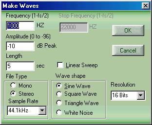
In order to generate audio signals, run the program and then select Edit/Make Waves. The following screen will appear:
Select a frequency, the amplitude, and the length of the desired signal. The sample rate of the waveform, the number of bits and the type of waveform should also be chosen at this point. Next, click on “OK” and the file will be created and the result will be found in the waveform display window.
DC5 and Live5 Forensics support a variety of sample rates. Your choice of sample rate depends on two factors – the frequency of the audio signal you want to generate and also the maximum sample rate supported by your sound card. If you are going to play the signal thru the output of your sound card, the maximum theoretical signal you can produce is defined as ½ the sampling rate. In actual practice, this is not achievable, because perfect brick wall filters cannot be created and “wrap around aliasing” signals will be produced when a frequency is produced which is greater than 0.5 X the sampling rate of your sound card. The most popular sample rate is 44.1 KHz, which will allow you to generate signals of from 1Hz to 22.050 KHz. Ultrasonic signals up to 96 KHz can be created by selecting the 192 KHz sampling rate, but this requires a sound card capable of 192 KHz sampling. Sub-sonic signals can be created down to 0.01 Hz (or 10 mHz (milliHertz)).
* Note: 1 Hz = 1 Cycle Per Second (cps)
The bit depth (or resolution) chosen will normally be 16 bit, but 8, 20 and 24 bit audio are also selectable. As with the Sample Rate selection, you must select a bit depth supported by your sound card if you wish to play the signal thru the sound card. Some low-end sound cards do not support anything greater than 16 bits.
As outlined before, the signal generator is capable of creating audio signals mathematically up to almost ½ the sample rate of the maximum capability of your sound card. The actual range of signals that can be generated starts at .01Hz on the low end. The highest frequency that can actually be generated is found by the following formula:
Fmax = (0.5 x Sample Rate)
In practice, the highest frequency that your sound card can deliver will be slightly below ½ the sampling rate. The reason for this is that sound cards and other devices with D/A and A/D converters will not be able to handle the theoretical maximum frequency suggested by their sample rate because they do not contain idealized brick wall anti-aliasing filters. Also, it is important to note that many sound cards do not specify their frequency response above 20 KHz, even though they may support 48, 96, or 192 KHz sampling rates. One of the reasons sound cards have a higher sampling rate is to be able to use output and input anti-aliasing filters with gentler slopes resulting in less phase shift at the top end of the audio spectrum.
Therefore, with a 96 KHz sound card any frequency from .01Hz to 48.000 KHZ can be input into the sound card by the Make Waves generator. However, the maximum frequency that the sound card can reproduce will depend on the quality of the sound card filters. Also, very few sound cards are DC coupled on their outputs, so very low frequencies may be impossible to achieve. If you need sub-sonic output signals, contact the various vendors of sound cards and ask if they have a model capable of response down to DC, or at least lower than 20 Hz. Another important thing to note is that cheap sound cards produce relatively high levels of output noise and distortion, so if you are interested in doing precision work, you will need to study the performance of the sound card that you purchase.
Frequency Reference: 1 KHz Sine Wave
%THD: Sine Wave
Frequency Response: Swept Sine Frequency or White or Pink Noise
Linearity: Triangle Wave
Linearity vs. Frequency: Swept Triangle
Slew Rate: Square Wave
Amplifier Transient Response and loop stability: Square Wave
The Make Waves function provides the ability to mathematically create near perfect sine waves, square wave and triangle waves. Sine waves are those which follow the rules of simple harmonic motion (f(t) = Sin ωt +φ). A square wave is the summation of all of the odd harmonics of a fundamental frequency. Ideally, it has an infinite rise time followed by a zero slope which then repeats. In actually practice, the Diamond Cut square wave rise time is 1 sample long. The Diamond Cut square wave is symmetrical having a 50 % duty cycle with equal areas under the positive and negative portions of its waveform. A triangle wave consists of a linear positive going slope followed by a linear negative going slope repeated cyclically. The Diamond Cut Triangle wave is also 50 % duty cycle and symmetrical in amplitude. The equations shown below can be used to calculate the Coefficients of a Fourier Series, Average Values and RMS Values for Square Waves or Triangle Waves:
Sine Wave

Square Wave
Triangle Wave
White Noise
The following chart summarizes the theoretical Harmonic Distortion components produced by the various waveforms provided by the "Make Waves" generator:
Square Wave:
Coefficient of Fourier Series = Cn = 2Aav [Sin (nπt0 / T) / nπt0 / T]
wherein Aav = Average Value* = A (t0 / T)
(Arms = RMS Value = A(t0/T)^1/2)
Triangle Wave:
Coefficient of Fourier Series = Cn = 2Aav [Sin (nπt1 / T) / nπt1 /T]^2
wherein Aav = Average Value* = A(t1/T)
(Arms = RMS Value = A(2t1/3T)^1/2)
* Note: Average Value = Average rectified full wave value of waveform
DC5 and Live5 Forensics can be used to create a signal whose frequency changes over time in a linear fashion. By selecting the “Linear Sweep” checkbox, this function will be enabled. The user can then specify a start and stop frequency and the resulting file will change frequency over the length of the file in a linear fashion. It should be noted that the start and stop frequencies can be chosen to result in a file either increasing or decreasing in frequency.
Generating White Noise
White Noise is random noise that is characterized as containing equal energy per unit frequency in Hertz (Hz). White Noise is sometimes referred to as Johnson, shot, or thermal noise. White noise derives its name from the analogous definition of white light. Audio white noise can be created using the Diamond Cut “Make Waves” function. To generate White Noise, simply click the appropriate box in the Make Wave screen. Note: When White noise is selected, all other frequency or sweep settings are ignored, but the signal amplitude function is still used. It is important to note that White noise, when viewed on the Diamond Cut spectrum analyzer will produce a flat line, because it is weighted in equal Hz buckets. This is in contrast to most Real Time Analyzers (RTA’s) that you purchase in the sound store which are usually 1/3rd octave weighted.
Generating Pink Noise
Pink Noise is random noise that is characterized as containing equal energy per unit octave. It is useful in audio testing in which an octave based Real Time Analyzer is used as the measurement device. Diamond Cut can produce Pink noise from White Noise by the following simple conversion technique. Follow these steps:
1. Generate White Noise with the desired Length, Sampling Rate, Bit depth at an amplitude of –3 dB.
2. Bring up the Paragraphic Equalizer
3. Run the preset called “White to Pink Noise Converter:”
4. The resultant file produced will be Pink Noise
Pink Noise, when viewed on the Diamond Cut spectrum analyzer will show a negative going slope to its spectral distribution. Pink noise is most suited to be used with Octave weighted analyzers (RTA’s) or by applying the Diamond Cut Pink to White Noise converter preset found in the paragraphic equalizer which will convert pink noise to a flat line for easy interpretation.
Generating Brown & Seismic Noise
Brown Noise is a form of random noise exhibiting a Gausian distribution, which mimics Brownian motion. Its power spectrum is proportional to 1 / f^2 exhibiting a –6dB / Octave slope. This form of noise is useful in scientific experiments which need to mimic Brownian motion and can be created by converting Random white noise to Brown Noise with the appropriate file converter found under the Multifilter. Seismic Noise is a special case of Brown noise with its bandwidth limited to below 20 Hz and can also be created using the appropriate converter found under the Multifilter.
Generating a phase shift between two Signals
Since the Diamond Cut Make Waves generator can create a stereo wavefile, it may be useful to generate a phase shift between the left and right channel signal. For example, in some cases, you may want to simulate a surround sound signal which is accomplished by placing one channel in quadrature with respect to the other (+/-90 degrees phase shifted). Also, three-phase open-delta signals can be created by shifting one channel with respect to the other by 120 degrees. Phase shifting one channel with respect to the other is accomplished in a few simple steps:
1. Create the Stereo waveform that you desire using the Make Waves generator.
2. Use the Sine, Square, or Triangle Waveforms. (Phase shifting random noise is of little practical value).
3. Bring up the File Conversion Filter
4. Bring up the XY plotter found under the View Menu
5. Preview the File Conversion Filter
6. Vary the Time Offset function until you obtain the desired phase shift as displayed on the XY display.
7. Run the File Conversion Filter
8. The resultant file will have the phase shifted between the Left and Right channels as per your preview operation.
Sometimes it is desirable to modify the shape of a waveform or to create a completely new waveform from scratch. Both can be done with the Edit/Make Waves function and the Pencil Tool available under the Edit menu. Note: usage of the Pencil tool requires that the waveform be zoomed in sufficiently to display single cycles. An example of modifying an existing waveform might be the creation of a “dropped Sine wave” or a clipped sine wave. To achieve this, make a regular sine wave and then use the Pencil tool to draw out one or more cycles or use it to square off the top of the waveform.
Alternatively, you may want to create your own custom waveform. In this case, merely use Make Waves to create silence by turning the Amplitude control down to its minimum after choosing a file length, and then click on OK. Next, use the Pencil function to edit or draw the desired single or multiple cycle waveform. This arbitrary waveform may be repeated for as many cycles as desired by using the Copy and Paste Insert function found under the Edit menu.
Specifications*: (specifications subject to change without notice)
Frequency Range: .01HZ to 96 KHz (23 Octaves)
Sampling Rate: 11.025 to 192.000 KHz
Signal Resolution: 8, 16, 20, or 24 bits
Signal Levels: -97db to 0db
Types of Signals: Sine, Square, Triangle, Random Noise
Frequency Resolution (data entry & data output): < 0.0001 Hz
Frequency Accuracy: Sound Card Dependent
Amplitude Resolution (data entry & data output): < 0.01 dB
Amplitude Accuracy: Sound Card Dependent
Sine Wave Purity: < 0.006% THD @ 44.1 KHz, 16 bit @ -1 dB Output (not including sound card influence)
Phase Jitter: Sound Card dependent
Minimum Length of Signal File: 10 mSec (milliseconds)
Maximum Length of Signal File: 600 Seconds
Length of Signal which may be output by sound card:Time can be unlimited by using DC5 Live5 Forensics “Play Loop” function.
*Note: The ultimate performance of the Diamond Cut Make Waves generator is determined by the quality of the sound card in your system
Copyright, Enhanced Audio, Inc. 2003 and Diamond Cut Productions, Inc, 2003